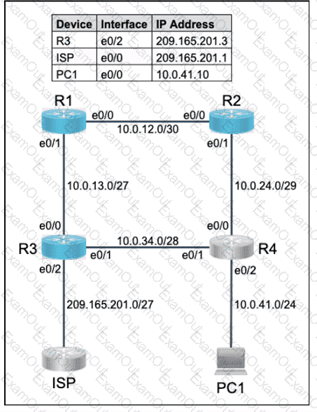
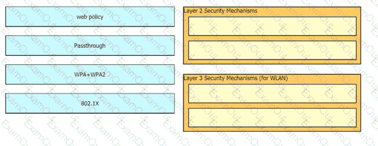
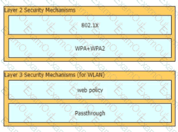
Drag and drop the Cisco Wireless LAN Controller security settings from the left onto the correct security mechanism categories on the right.

Refer to the exhibit.
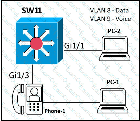
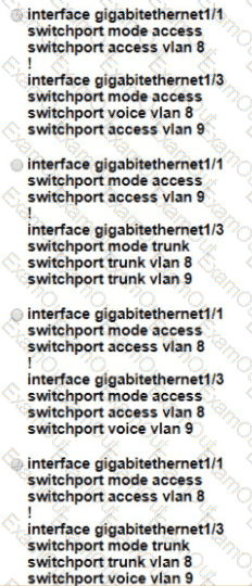
An administrator must configure interfaces Gi1/1 and Gi1/3 on switch SW1. PC-1 and PC-2 must be placed in the Data VLAN and Phone-1 must be placed in the Voice VLAN Which configuration meets these requirements?
What is the path for traffic sent from one user workstation to another workstation on a separate switch In a three-tier architecture model?
Refer to the exhibit.
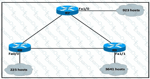
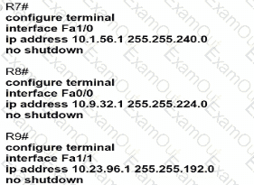
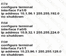
An IP subnet must be configured on each router that provides enough addresses for the number of assigned hosts and anticipates no more than 10% growth for new hosts. Which configuration script must be used?
A)
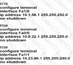
B)
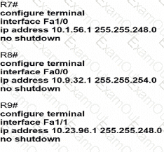
C)
D)
Where does a switch maintain DHCP snooping information?
What is a syslog facility?
What are two recommendations for protecting network ports from being exploited when located in an office space outside of an IT closer? (Choose two.)
Refer to the exhibit.
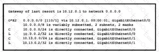
If configuring a static default route on the router with the ip route 0.0.0.0 0.0.0.0 10.13.0.1 120 command how does the router respond?
What is a function of the Cisco DNA Center Overall Health Dashboard?
What is a difference between RADIUS and TACACS+?
A network engineer must configure the router R1 GigabitEthernet1/1 interface to connect to the router R2 GigabitEthernet1/1 interface. For the configuration to be applied the engineer must compress the address 2001:0db8:0000:0000:0500:000a:400F:583B. Which command must be issued on the interface?
Refer to the exhibit.
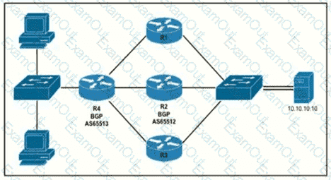
Router R4 is dynamically learning the path to the server. If R4 is connected to R1 via OSPF Area 20, to R2 via R2 BGP, and to R3 via EIGRP 777, which path is installed in the routing table of R4?
Topology:
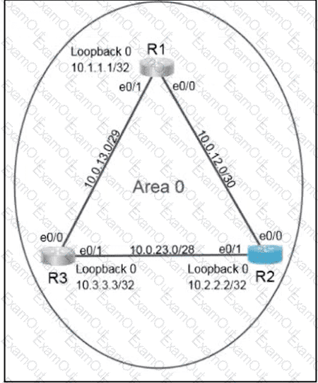
Configure OSPF routing for the network by completing the following tasks:
Task 1
Configure OSPF on R2. Ensure that R1 and R3 become neighbors.
Use process ID 30.
Use 10.22.22.22 as the router ID.
Under the OSPF process, advertise the following specific prefixes:
10.0.23.0/28
10.0.12.0/30
Task 2
Ensure that R2 always becomes the designated router (DR).
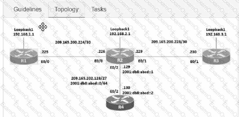
Connectivity between four routers has been established. IP connectivity must be configured in the order presented to complete the implementation. No dynamic routing protocols are included.
1. Configure static routing using host routes to establish connectivity from router R3 to the router R1 Loopback address using the source IP of 209.165.200.230.
2. Configure an IPv4 default route on router R2 destined for router R4.
3. Configure an IPv6 default router on router R2 destined for router R4.
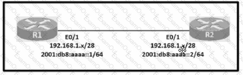
Configure IPv4 and IPv6 connectivity between two routers. For IPv4, use a /28 network from the 192.168.1.0/24 private range. For IPv6, use the first /64 subnet from the 2001:0db8:aaaa::/48 subnet.
1. Using Ethernet0/1 on routers R1 and R2, configure the next usable/28 from the 192.168.1.0/24 range. The network 192.168.1.0/28 is unavailable.
2. For the IPv4 /28 subnet, router R1 must be configured with the first usable host address.
3. For the IPv4 /28 subnet, router R2 must be configured with the last usable host address.
4. For the IPv6 /64 subnet, configure the routers with the IP addressing provided from the topology.
5. A ping must work between the routers on the IPv4 and IPv6 address ranges.
Using direct sequence spread spectrum, which three 2.4-GHz channels are used to limit collisions?
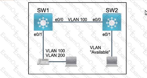
All physical cabling between the two switches is installed. Configure the network connectivity between the switches using the designated VLANs and interfaces.
1. Configure VLAN 100 named Compute and VLAN 200 named Telephony where required for each task.
2. Configure Ethernet0/1 on SW2 to use the existing VLAN named Available.
3. Configure the connection between the switches using access ports.
4. Configure Ethernet0/1 on SW1 using data and voice VLANs.
5. Configure Ethemet0/1 on SW2 so that the Cisco proprietary neighbor discovery protocol is turned off for the designated interface only.
Topology:
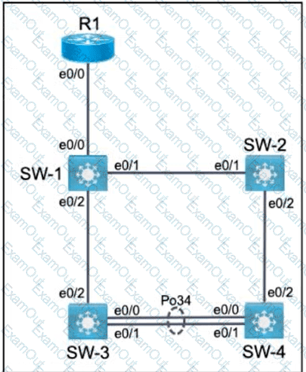
All relevant ports are preconfigured as IEEE 802.1Q trunks.
Task 1
Configure SW-1 port Ethernet0/0 to permit only VLANs 5 and 6.
Task 2
Configure ports Ethernet0/1 on SW-1 and SW-2 to use VLAN 77 as the native VLAN.
Task 3
Configure SW-2 port Ethernet0/2 to permit only VLAN 6.
Task 4
Using LACP, create a Port-Channel between SW-3 and SW-4.
Combine Ethernet0/0 and Ethernet0/1 into a Port-Channel while leaving the existing trunk configurations intact.
Assign Port-Channel number 34.
Only SW-3 must initiate LACP negotiations.
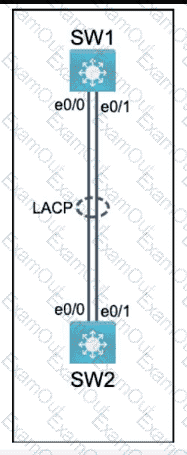
Physical connectivity is implemented between the two Layer 2 switches,
and the network connectivity between them must be configured.
I . Configure an LACP EtherChanneI and number it as 44; configure it
between switches SWI and SW2 using interfaces EthernetO/O and
Ethernet0/1 on both sides. The LACP mode must match on both ends.
2. Configure the EtherChanneI as a trunk link.
3. Configure the trunk link with 802. Iq tags.
4. Configure VLAN ' MONITORING ' as the untagged VLAN of the
EtherChannel.
==================
Guidelines
This is a lab item in which tasks will be performed on virtual devices.
• Refer to the Tasks tab to view the tasks for this lab item.
• Refer to the Topology tab to access the device console(s) and perform the tasks.
• Console access is available for all required devices by clicking the device icon or using
the tab(s) above the console window.
• All necessary preconfigurations have been applied.
• Do not change the enable password or hostname for any device.
• Save your configurations to NVRAM before moving to the next item.
• Click Next at the bottom of the screen to submit this lab and move to the next question.
• When Next is clicked, the lab closes and cannot be reopened.
All physical cabling is in place. Router R4 and PCI are fully configured and
inaccessible. R4 ' s WAN interfaces use .4 in the last octet for each subnet.
Configurations should ensure that connectivity is established end-to-end.
1 . Configure static routing to ensure RI prefers the path through R2 to
reach only PCI on R4 ' s LAN
2. Configure static routing that ensures traffic sourced from RI will take
an alternate path through R3 to PCI in the event of an outage along
the primary path
3. Configure default routes on RI and R3 to the Internet using the least number of hops
Guidelines
This is a lab item in which tasks will be performed on virtual devices.
• Refer to the Tasks tab to view the tasks for this lab item.
• Refer to the Topology tab to access the device console(s) and perform the tasks.
• Console access is available for all required devices by clicking the device icon or using
the tab(s) above the console window.
• All necessary preconfigurations have been applied.
• Do not change the enable password or hostname for any device.
• Save your configurations to NVRAM before moving to the next item.
• Click Next at the bottom of the screen to submit this lab and move to the next question.
• When Next is clicked, the lab closes and cannot be reopened.