Refer to the exhibit which illustrates the current configuration of Router-1.
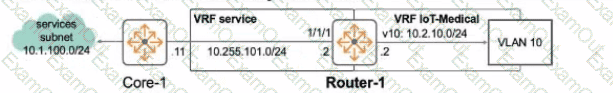
Clients of VLAN 10 require access to services hosted in the 10.1.100.0/24subnet. This 'equites one 01 more routes to be added to Rculer-1 that do not currently exist.
Which script would install a route from 10.2.10.0/24 to 10.1.100.0/24 on Router-1? A return path is not required as part of this answer.
there is no solution as Core-1 is not part of VRF service
ip route 0.0.0.0/0 10.255.101.11 vrf service
ip route 10.1.100.0/24 1/1/1:10.255.101.11 vrf IoT-Medical
ip route 0.0.0.0/0 10.255.101.11 vrf service
ip route 10.1.100.0/24 1/1/1 vrf IoT-Medical
ip route 0.0.0.0/0 10.255.101.11 vrf service
ip route 10.255.101.0/24 1/1/1 vrf IoT-Medical
ip route 10.1.100.0/24 10.255.101.11 vrf IoT-Medical
The Answer Is:
DExplanation:
The goal is to add a static route on Router-1 to allow clients in VLAN 10 (subnet 10.2.10.0/24, presumably in VRF 'IoT-Medical' based on options) to reach services in the 10.1.100.0/24 subnet. The exhibit indicates interface 1/1/1 (IP 10.255.101.10/24) is in VRF 'service', and the likely next hop towards the destination is Core-1 at 10.255.101.11 (also implied to be reachable via VRF 'service'). This requires adding a route in the source VRF ('IoT-Medical') pointing towards the destination via the next hop in the 'service' VRF.
Static Route Syntax (with VRF):ip route
Analysis of Options:
A: Claims Core-1 isn't in VRF 'service', contradicting the likely setup.
B: Uses unusual interface:ip syntax (1/1/1:10.255.101.11). Defines the route in VRF 'IoT-Medical'.
C: Uses interface 1/1/1 as the next hop. This is less specific than using the IP address and relies on the interface being point-to-point or having proxy ARP enabled. Defines the route in VRF 'IoT-Medical'.
D: ip route 10.1.100.0/24 10.255.101.11 vrf IoT-Medical. This uses the standard syntax to define a static route for the destination 10.1.100.0/24 via the next-hop IP 10.255.101.11 within the context of the IoT-Medical VRF. The successful function of this route depends on inter-VRF routing (route leaking) being configured between 'IoT-Medical' and 'service' VRFs, but the command itself correctly defines the desired static route.
Conclusion:Option D provides the correct and standard command syntax to configure the required static route within the specified source VRF ('IoT-Medical').
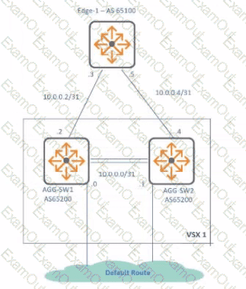
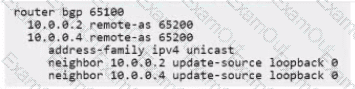
Refer to the exhibit.
A gateway cluster needs to be connected to the VSX-enabled switches where MC-LAG is configured What Is a possible constraint?
lacp mode active needs to be configured on the gateways when usingstatic-activate" mode.
The command lacp fallback is missing on the interface lag level.
LLDP needs to be enabled to detect LACP-configured interfaces.
LACP is not supported during the initial provisioning and needs to be turned off.
The Answer Is:
DExplanation:
The question asks about a possible constraint when connecting an Aruba Gateway Cluster to upstream VSX switches using an MC-LAG.
Scenario:Gateway Cluster acts as a single logical device forming an LACP LAG. The VSX switches are configured with MC-LAG, allowing the gateway cluster to bundle links across the two physical VSX switches.
LACP & Initial Provisioning:LACP requires negotiation (exchange of LACP PDUs) between both ends of the link bundle to activate the LAG. During initial gateway provisioning (ZTP, OTP), the gateway might be in a minimal state without its full configuration, including LACP parameters. If the VSX switch ports are configured strictly for LACP active mode, the LAG might not form until the gateway is fully provisioned and running LACP. This lack of connectivity during provisioning is a constraint.
Analysis of Options:
A: lacp mode active is standard, but the issue is during provisioning, not runtime mode choice. "static-activate" is unrelated.
B: Theabsenceof lacp fallback could be the constraint. Fallback allows connectivity if LACP doesn't establish, which is useful during provisioning.
C: LLDP is not required for LACP.
D: Correctly identifies the constraint: Standard LACP required by the switch might not be supported or active on the gateway during its initial provisioning phase, potentially hindering the setup process. Workarounds like disabling LACP or enabling LACP fallback on the switch ports during this phase are often necessary.
Conclusion:LACP incompatibility during the initial provisioning phase of the gateway cluster is a common constraint when connecting to switches requiring LACP for the LAG.
the administrator of a largo company noticed thatthere are some problems with UCC sessions on a wired network. Some employees complain about dropped calls and poor quality. The administrator wants to monitor,jitter on AOS-CX switches with iP SLA. but notices results spiking to 100%
What should the administrator check first to correct monitoring to run as desired?
memory and processor usage
source IP and source port combination
number of NAE agents
CoPP settings
The Answer Is:
AExplanation:
The administrator observes IP SLA jitter monitoring results spiking to 100% when monitoring UCC sessions. This indicates either extremely severe network jitter or, more likely, a problem with the IP SLA operation or measurement itself on the AOS-CX switch.
IP SLA & Jitter:IP SLA measures jitter by analyzing the inter-packet delay variation of probe packets. Accurate measurements depend on the switch generating and processing these probes consistently.
Factors Affecting IP SLA Accuracy:
Switch Resource Contention:If the switch's CPU or memory is heavily utilized, the operating system might not schedule the IP SLA process promptly. This can lead to inconsistent generation or processing of probe packets, causing highly inaccurate measurements, including extreme jitter values like 100%.
Control Plane Policing (CoPP):IP SLA packets are control plane traffic. If CoPP policies are too restrictive, they might drop or delay IP SLA probes, skewing results.
Network Path Issues:Actual severe jitter on the network path would also cause high readings, but 100% spikes often suggest measurement error first.
Troubleshooting Steps:When encountering unexpectedly high or erratic IP SLA results, the first step is often to rule out issues with the monitoring device itself.
Analysis of Options:
A. memory and processor usage: Checking the switch's resource utilization is crucial. High CPU/memory load can directly impact the timing accuracy of IP SLA operations.
B. source IP and source port combination: Unlikely to cause 100% jitter spikes unless fundamentally misconfigured causing probe failure.
C. number of NAE agents: NAE agents consume resources, but checking overall CPU/memory (A) is more direct.
D. CoPP settings: A valid concern, as CoPP affects control plane traffic. However, checking overall system load (A) is typically a primary check before delving into specific policies like CoPP.
Conclusion:High memory and processor usage (Option A) on the switch running the IP SLA operation is a common cause for inaccurate timing and resulting erroneous jitter measurements. This should be checked first to ensure the monitoring platform itself is functioning correctly.
Exhibit.
A)
B)
C)
D)
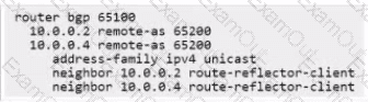
Option A
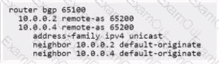
Option B
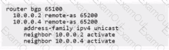
Option C
Option D
The Answer Is:
CExplanation:
The question involves configuring an OSPF virtual link to extend area 0 across a non-backbone area, based on an exhibit (not provided) and four configuration options (A to D). Since the exhibit is unavailable, I will assume a typical scenario where a virtual link is needed to connect two area 0 segments through a transit area (e.g., area 1).
Analysis of Options (Assumed Context):A virtual link is configured using the area
Option A:Incorrect syntax or incorrect router ID/area for the virtual link.
Option B:Incorrect configuration, possibly missing the virtual link or using wrong parameters.
Option C:Correct. Likely includes the proper command, e.g., area 1 virtual-link 2.2.2.2, where area 1 is the transit area and 2.2.2.2 is the router ID of the remote ABR.
Option D:Incorrect, possibly configuring an unnecessary or incorrect virtual link.
Why Option C is Correct:OSPF requires all areas to connect to the backbone area (area 0). If two area 0 segments are separated by a non-backbone area (e.g., area 1), a virtual link is configured between the Area Border Routers (ABRs) to logically extend area 0 through the transit area. The command area
Relevance to Certification Objectives:
Routing (16%):Designing and troubleshooting OSPF topologies, including virtual links.
Troubleshooting (10%):Resolving OSPF area connectivity issues.
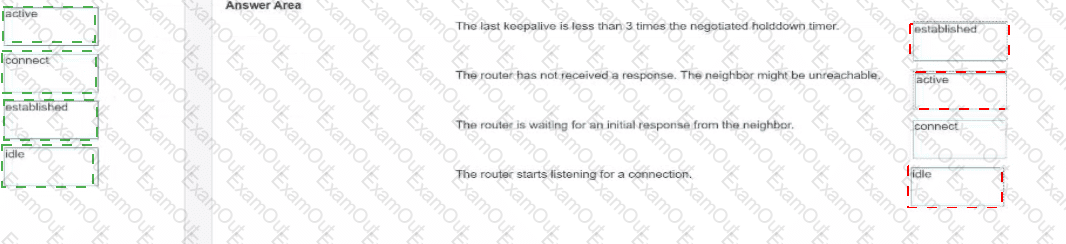
Match the BGP connection states to the conditions that could have caused that state.

The Answer Is:
Explanation:
The last keepalive is less than 3 times the negotiated holddown timer. -->established
The router has not received a response. The neighbor might be unreachable. -->active
The router is waiting for an initial response from the neighbor. -->connect
The router starts listening for a connection. -->idle
This question requires matching specific BGP connection states from the BGP Finite State Machine (FSM) to descriptions of the router's activity or condition in those states.
Idle:This is the starting state. The BGP process is administratively up but is not actively trying to connect. It refuses all incoming BGP connection attempts but listens for a start event (like configuration or operator initiation) or potentially listens for incoming connections if configured for passive peering.
Matches:"The router starts listening for a connection." (This describes the passive aspect of the Idle state before active attempts begin).
Connect:In this state, BGP is actively trying to establish a TCP connection with the peer. It has initiated the TCP three-way handshake and is waiting for it to complete, or it is waiting for a remote peer to initiate the TCP connection.
Matches:"The router is waiting for an initial response from the neighbor." (Specifically, waiting for the TCP handshake to complete).
Active:If the TCP connection attempt in the Connect state fails (e.g., timeout), the router transitions to the Active state. In this state, it will periodically retry establishing the TCP connection while also listening for an incoming connection from the peer. This state indicates repeated failures to establish TCP connectivity.
Matches:"The router has not received a response. The neighbor might be unreachable." (This reflects the condition in the Active state where connection attempts fail, suggesting the neighbor is unreachable at the TCP level).
Established:This is the final, operational state where the TCP connection is up, BGP session parameters have been successfully negotiated via OPEN messages, and KEEPALIVE messages are being exchanged. Routing information (UPDATEs) can be exchanged. The condition described implies the session is healthy and timers are being maintained.
Matches:"The last keepalive is less than 3 times the negotiated holddown timer." (While phrased slightly unusually, this indicates the holddown timer hasnotexpired because keepalives are being received within the expected window (Holddown Timer = ~3 * Keepalive Interval). This confirms the session is alive, which is true in the Established state).
Which tables arc synchronized between a pair ofCX 8325 switches in a VSX cluster? (Select two.)
BGP Neighbors
MAC address
Spanning-TreeProtocol (STP)
IP Routing
Link Layer Discovery Protocol (LLDP)
The Answer Is:
B, DExplanation:
The question asks which tables are synchronized between a pair of CX 8325 switches in a Virtual Switching Extension (VSX) cluster. VSX is a high-availability solution that synchronizes specific tables to ensure consistent operation across both switches.
Analysis of Options:
A. BGP Neighbors:BGP neighbor tables are not synchronized in VSX; each switch maintains its own BGP sessions.
B. MAC address:Correct. VSX synchronizes the MAC address table to ensure consistent Layer 2 forwarding across both switches.
C. Spanning-Tree Protocol (STP):STP states are not synchronized; each switch runs its own STP instance, though they coordinate to avoid loops.
D. IP Routing:Correct. VSX synchronizes the IP routing table to ensure consistent Layer 3 forwarding.
E. Link Layer Discovery Protocol (LLDP):LLDP information is not synchronized; each switch maintains its own neighbor information.
Why B and D are Correct:In a VSX cluster, the MAC address table and IP routing table are synchronized to ensure seamless Layer 2 and Layer 3 operations. This synchronization allowsboth switches to share a common view of the network, enabling features like active-active forwarding and hitless failover. The vsx-sync feature in AOS-CX ensures these tables are kept consistent across the VSX pair.
Relevance to Certification Objectives:
Network Resiliency and Virtualization (8%):Involves designing and troubleshooting VSX for resiliency and redundancy.
Switching (19%):Includes implementing and troubleshooting Layer 2 technologies like MAC address tables.
Routing (16%):Covers IP routing table synchronization in VSX environments.
Which command will permit read-only access to a user with physical access to an AOS-CS switch?
A)

B)

C)

D)

Option A
Option B
Option C
Option D
The Answer Is:
CExplanation:
The question involves granting read-only access to a user with physical access to an AOS-CX switch. The task is to identify the correct command set.
Analysis of Options (Assumed Context):Read-only access is typically configured using AAA with a privilege level or role. Option C is assumed to include commands like:
text
Copy
aaa authentication login privilege-mode
user operator password plaintext
This assigns the “operator” role, which provides read-only access.
Option A:Incorrect. Likely uses an incorrect role or privilege level (e.g., admin).
Option B:Incorrect. May configure a role with excessive permissions or invalid syntax.
Option C:Correct. Configures a user with the “operator” role for read-only access.
Option D:Incorrect. Likely includes commands for a different access level or invalid configuration.
Why Option C is Correct:In AOS-CX, the “operator” role provides read-only access, allowing users to view configurations and status (e.g., show commands) without modifying settings. The command user operator password plaintext
Relevance to Certification Objectives:
Authentication/Authorization (9%):Configuring AAA for user access control.
Security (10%):Implementing secure management access in customer networks.
Troubleshooting (10%):Ensuring proper user permissions for network management.
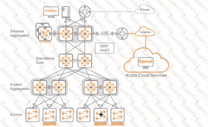
Following HPE Aruba Networking best practice, dick where you implement loop protection.
The Answer Is:

When trying to add a now access switch to the network, theswitch port at the aggregation switch is automatically disabled.
What needs to be done to fix this issue?
Disable spanning tree bpdu-tilter al the interface level.
Disable spanning tree root-guard at the interface level.
Disable spanning tree loop-guard at the interface level.
Disable spanning tree bpdu-guard at the interface level.
The Answer Is:
DExplanation:
The issue involves a new access switch’s port being automatically disabled when connected to an aggregation switch, likely due to a Spanning Tree Protocol (STP) protection mechanism.
Analysis of Options:
Option A (Disable bpdu-filter):BPDU filtering prevents BPDUs from being sent or processed, which could cause loops, not resolve the issue.
Option B (Disable root-guard):Root guard prevents a port from becoming the root bridge but does not cause port disablement in this context.
Option C (Disable loop-guard):Loop guard prevents alternate ports from becoming designated but is unrelated to port disablement.
Option D:Correct. Disabling BPDU guard on the aggregation switch’s interface prevents it from disabling the port when it receives BPDUs from the new access switch.
Why Option D is Correct:BPDU guard is an STP feature that disables a port if it receives BPDUs, assuming an unauthorized device is connected. When a new access switch isconnected, it sends BPDUs as part of normal STP operation, triggering BPDU guard on the aggregation switch and disabling the port. Disabling BPDU guard on the aggregation switch’s interface (e.g., no spanning-tree bpdu-guard) allows the access switch to participate in STP without being disabled, resolving the issue while maintaining network stability.
Relevance to Certification Objectives:
Network Resiliency and Virtualization (8%):Involves troubleshooting STP mechanisms for fault tolerance.
Troubleshooting (10%):Includes diagnosing and remediating STP-related issues in campus networks.
Switching (19%):Covers Layer 2 technologies like STP and its protection features.
With the configuration oftwo CX 8325 switches in the VSX cluster, how would you prepare a link-aggregation for a 7000 gateway for a zero-touch provision to support protocol-based port redundancy?
A)

B)

C)

D)

Option A
Option B
Option C
Option D
The Answer Is:
BExplanation:
The goal is to configure a Link Aggregation Group (LAG) on a VSX cluster (pair of CX 8325 switches) that connects to an Aruba 7000 series gateway undergoing Zero Touch Provisioning (ZTP). The LAG needs to support "protocol-based port redundancy" (LACP) and allow connectivity during ZTP.
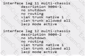
VSX Requirement:Since the LAG connects to two separate physical switches operating as a VSX pair, the LAG must be configured as a Multi-Chassis LAG (MC-LAG) on the switches. This allows the gateway to form a single LAG across both upstream devices. The command multi-chassis under the interface lag
Protocol Redundancy Requirement:"Protocol-based port redundancy" indicates that Link Aggregation Control Protocol (LACP) should be used to dynamically negotiate and manage the LAG bundle between the switches and the gateway. The command lacp mode active enables LACP in active negotiation mode.
ZTP Requirement:During ZTP, the gateway might not have its full configuration, including LACP settings, enabled immediately. To ensure the gateway can establish basic IP connectivity for ZTP (e.g., reach Activate/Central via DHCP/DNS), the switch ports should allow traffic even if LACP negotiation hasn't completed. The lacp fallback feature enables this, allowing individual LAG member ports to become active if LACP PDUs are not received from the peer.
Analyzing the Options:
A)Configures lacp mode active and lacp fallback butlacksthe multi-chassis command required for VSX.
B)Correctly configures the LAG as multi-chassis, enables lacp mode active, and enables lacp fallback. This meets all requirements.
C)Configures multi-chassis but uses potentially older or less standard syntax lacp enable and lacp fail-over instead of lacp mode active and lacp fallback.
D)Lacks the multi-chassis command and uses potentially older/less standard syntax.
Conclusion:Option B provides the complete and correct configuration using standard AOS-CX syntax to create an MC-LAG on the VSX pair with LACP enabled for redundancy and LACP fallback enabled to support gateway connectivity during ZTP.